Prerequisite - Chapter 1
- Install Rust using
rustup- https://www.rust-lang.org/tools/install - Setup git - you will also need to set your
sshkey in Github to: - Clone repository:
git clone git@github.com:LechevSpace/nanosat-workshop.git - Install RiscV toolchain:
rustup target install riscv32imac-unknown-none-elf - Build the application:
cd nanosat-workshop && cargo build
System overview

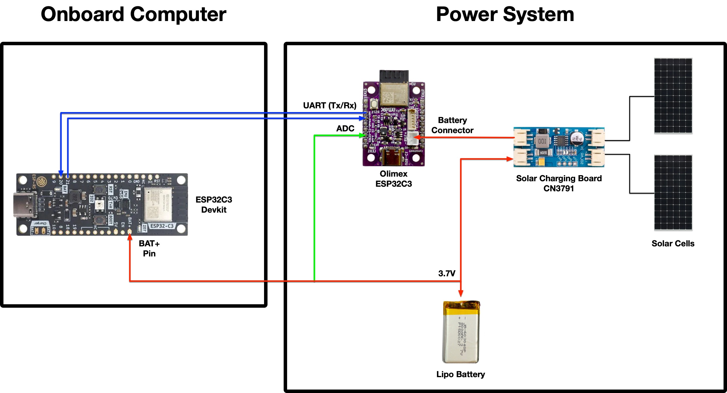
2 solar panels connected to solar charging board CN 3791 which is connected to system (VCC & GND) to Olimex ESP32-C3 (rev. 1) and the ESP32-C3 Rust dev kit (tag v1.2) by Espressif
The output for the battery on the solar charger is connected a switch to disconnect power going towards the battery and then connected to a LiPo 3.7V battery of 250 mAh (Datasheet).
On the connection to the battery, there's also a pin for ADC to the Olimex board for taking measurements of the battery. This allows us to read the battery percentage without charging it through the solar charger or USB (e.g. when we're programming the board).
Charge voltage 4.2V, nominal voltage 3.7V, cut-off voltage 3.0V
Recommended charge current 50mA
Max charge current 125mA
Recommended discharge current 125mA
Max discharge current 250mA
Impedance 60mOhm at 1KHz
Operating temperature: at charge 0-55C, at discharge -25C+60C
Capacity loss after 500 cycles full charge/discharge at 20C: 20%
Dimensions 27x21x5mm
Bill of materials (BOM)

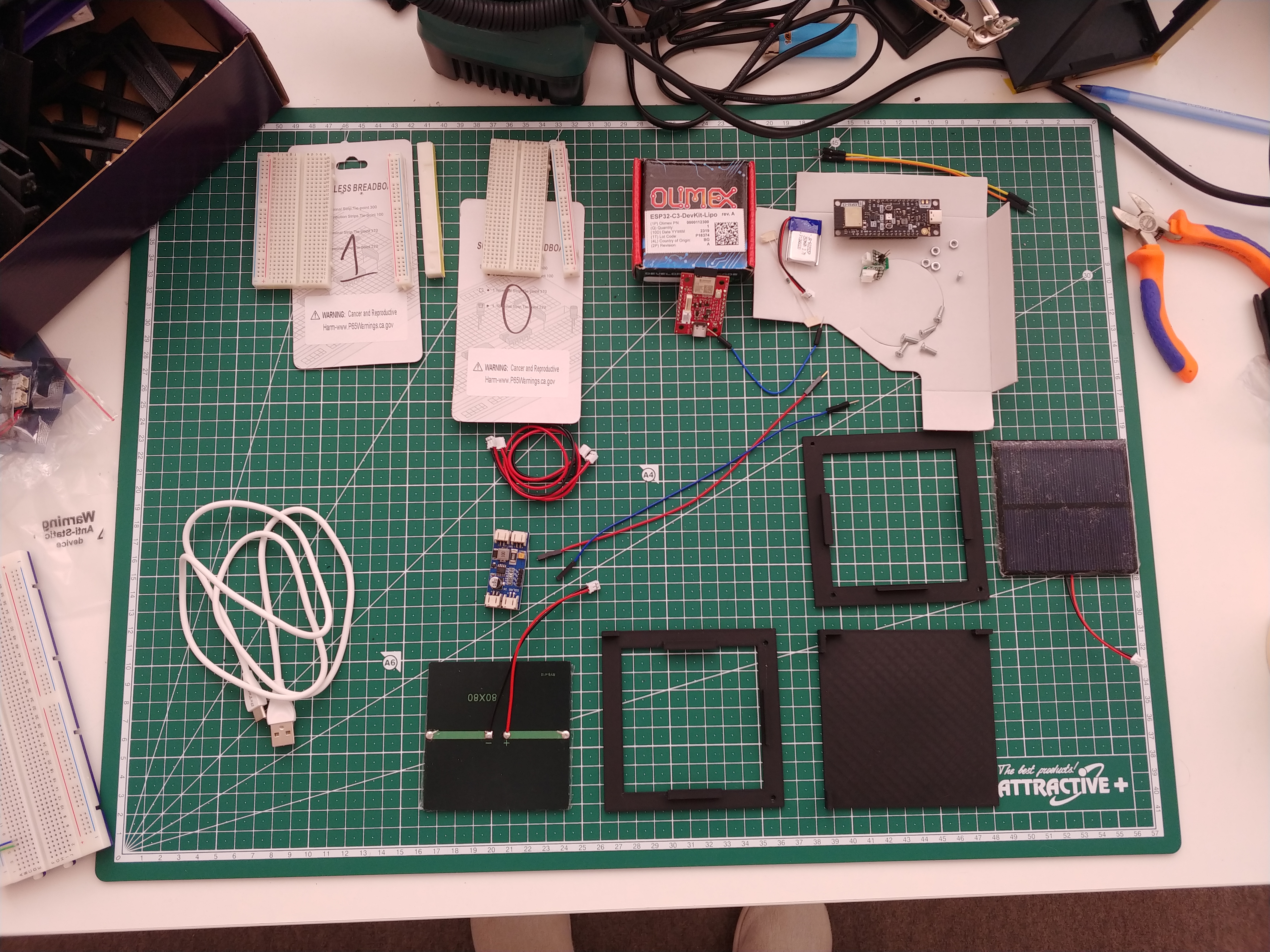
Components
-
1 x Olimex board (
ESP32-C3-DevKit-Lipo): https://www.olimex.com/Products/IoT/ESP32-C3/ESP32-C3-DevKit-Lipo/ -
1 x Espressif Rust board (ESP32-C3): https://www.espressif.com/en/products/devkits (
ESP32-C3-DevKit-RUST-1) -
LiPo Battery - 250 mAh or larger (3.0V cut-off, 3.7V nominal and 4.2V max, with overcharge and over-current protection)
-
2 x Breadboards (Dimensions 82x52x10mm, Power supply bus on top and bottom, Grid on 0.1" step)
-
2 x solar panels (80x80 mm, 6V) with JST-PH 2.0 male connectors (separately soldered)
-
1 x solar charger (CN3791 with 2 solar panel connectors JST-PH 2.0)
- Includes 2 cables JST-PH 2.0 (male) on both sides
-
2 x JST-PH to 2 pin header connectors for breadboarding
-
2 x resistors (470k Ohms, 1%) - used for the Voltage divider which we use to measure the battery
-
3 x male to male jumper cables - 2 for UART (RX & TX) and 1 for ADC.
-
2 x male to female jumper cables - for powering the Espressif board (BAT+ & GND pins) from the solar charger
-
USB-C to USB-B / USB-C to USB-C cable for programming (depends on your development machine)
Frame
- 5 x M3 L10 bolts
- 5 x M3 nuts
- 1 x 3D printed frame - consists of 3 distinct sides (bottom, front and right)
Board's applications
Both applications are structured in the following way to allow you to follow the exercises:
Application::init- initialise any peripheral that will be used for theApplication
Application:run- spawns all tasks on the embassy executor needed for ourApplication.power_system::Application::runonboard_computer::Application::runpower_system::Application::init
- An embassy task
fn run_*(..)for each exercise
Power System Application (power-system folder)
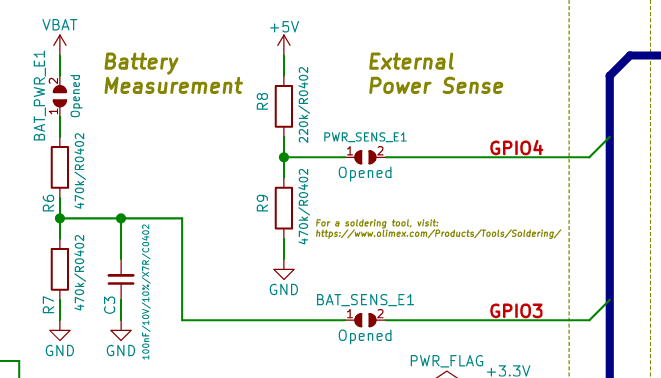
Battery and power sense

Onboard-computer (onboard-computer folder)
Peripherals
| Peripheral | Part number | Crate | Address |
|---|---|---|---|
| IMU | ICM-42670-P (Datasheet) | icm42670 | 0x68 |
| Temperature and Humidity | SHTC3 (Datasheet) | shtcx | 0x70 |
Exercises
Start with the power-system:
- Flashing Onboard LED - a blinky example for IO -
power_system::application::run_blinky - Battery measurement with ADC - measure and calculate the battery voltage and percentage -
power_system::application::run_battery_measurement_adc - Send Battery percentage over UART to the
onboard-computer-power_system::application::run_uart
Continue with the next exercises in the onboard-computer:
- Receive battery percentage over UART from the
power-system-onboard_computer::application::run_uart - GNSS receiver - parse NMEA 0183 sentences -
onboard_computer::application::run_gnss
Future ideas you can develop
In no particular order:
-
Power sense (
power-systemapplication)By soldering the jumper for
GPIO 4you can measure the voltage of the +5V Power in line. This allows you to know whether or not an external +5V has been provided (both from USB-C or other), that will charge the battery. Implement another status for the battery which is Charging/External power. -
IMU (
onboard-computerapplication) Using the I2C peripheral and the included IMU sensor on theonboard-computer, take readings of the -
Humidity and Temperature sensor (
onboard-computerapplication)